01/04/2025 5:01 a.m.
http://stage.cablematic.com/en/products/ip-server-rs-232-rs-422-rs-485-4-port-RS065/
http://stage.cablematic.com/en/products/ip-server-rs-232-rs-422-rs-485-4-port-RS065/
IP Server RS-232 RS-422 RS-485 (4-Port)
REF: RS065
OUTLET
Specifications
- 10/100 Mbps Ethernet with auto-detection.
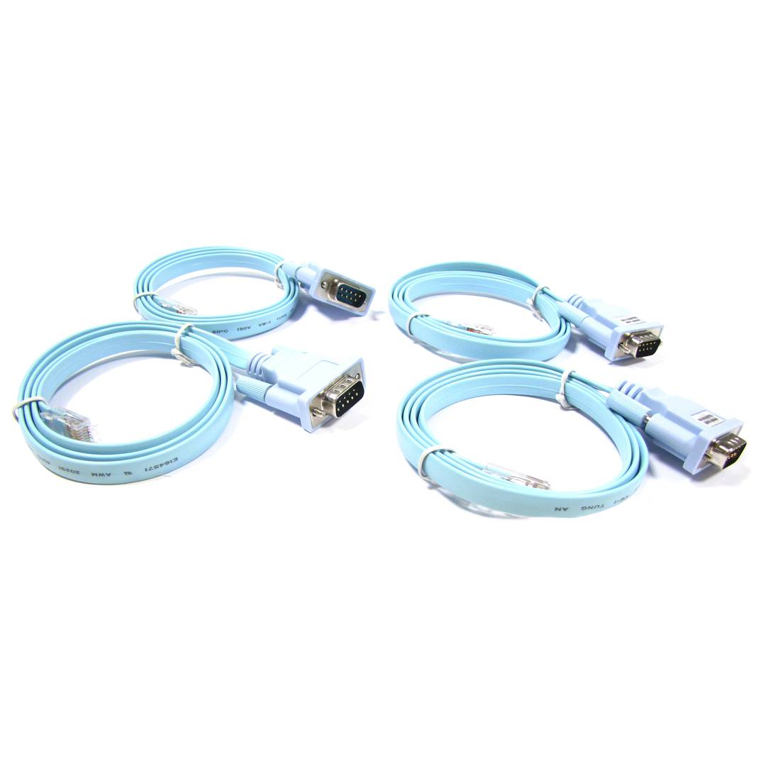
- It has 4 female RJ45 serial ports. 4 cables of type RJ45 male to DB9 male 1m long are supplied.
- The 4 serial ports can be compatible with RS-232, RS-422 and RS-485.
- Proprotection against voltage peaks of up to 600 W for each of the serial ports.
- Supports 2 and 4 threads for the RS-485 protocol.
PVP
€121.40
€19.42
Price including VAT:
€19.42
PVD
€103.92
€16.63
PVP: Retail price.
Check conditions.
PVP: Sale price to distributors.
Check conditions.
warranty
returns
OUTLET
Specifications
- 10/100 Mbps Ethernet with auto-detection.
- It has 4 female RJ45 serial ports. 4 cables of type RJ45 male to DB9 male 1m long are supplied.
- The 4 serial ports can be compatible with RS-232, RS-422 and RS-485.
- Proprotection against voltage peaks of up to 600 W for each of the serial ports.
- Supports 2 and 4 threads for the RS-485 protocol.
More info
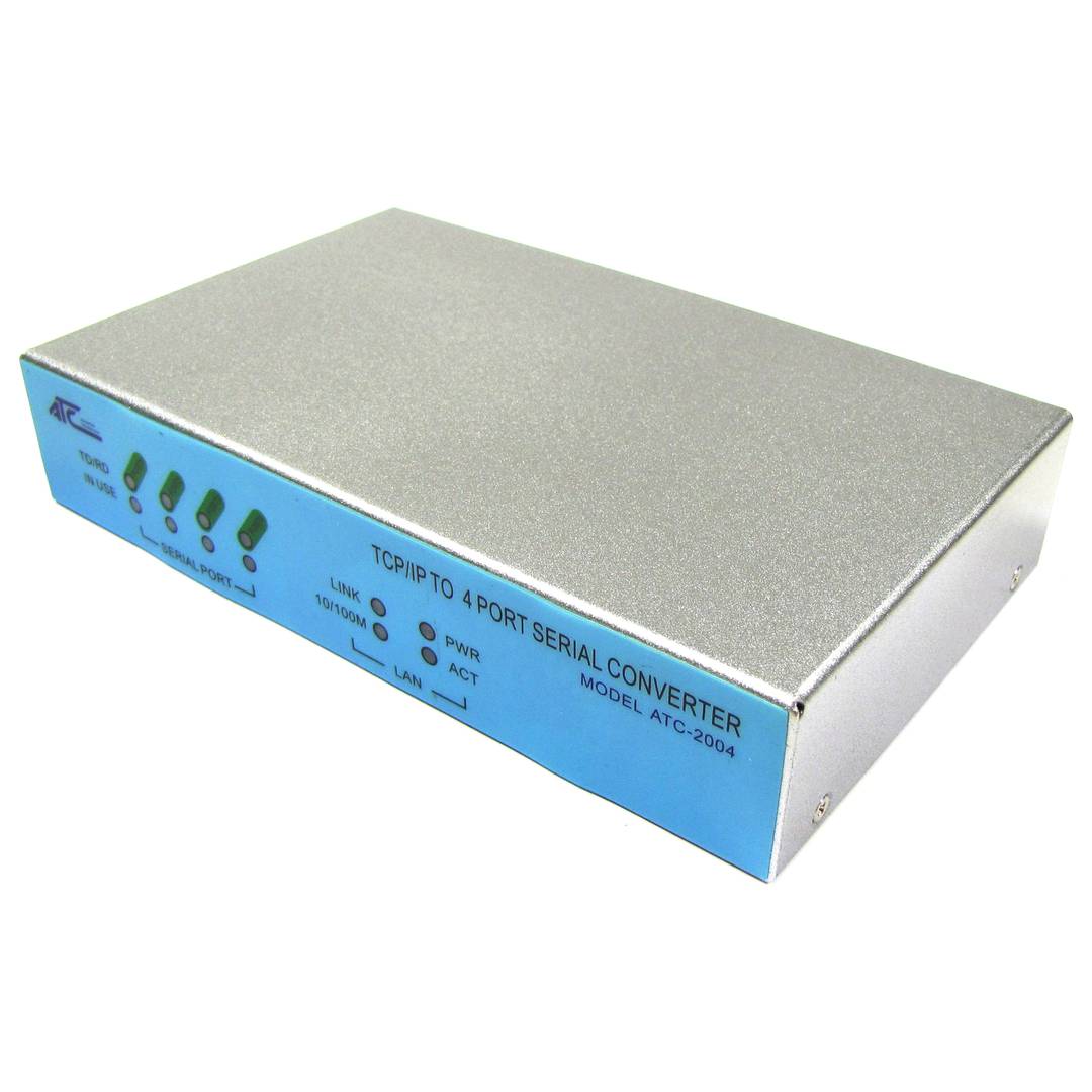
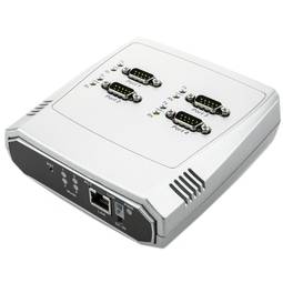
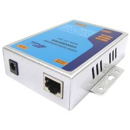
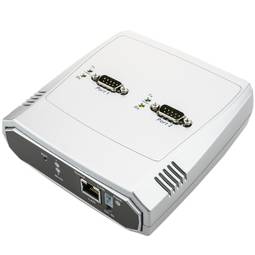
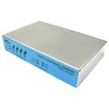
Server of 4 serial ports RS-232, RS-422 and RS-485 through Ethernet remotely using TCP/IP or UDP/IP protocols. It is a compact and robust device mounted on metal casing that has a female RJ45 connector (10/100 Mbps ethernet) and 4 male DB9 serial connectors (RS-232, RS-422 and RS-485 series). To access the serial port through LAN, simply install the supplied driver and Windows createsa virtual serial port on the computer. It is also possible to interconnect two serial servers between them through LAN (paired mode).
Specifications
Specifications
- 10/100 Mbps Ethernet with auto-detection.
- It has 4 female RJ45 serial ports. 4 cables of type RJ45 male to DB9 male 1m long are supplied.
- The 4 serial ports can be compatible with RS-232, RS-422 and RS-485.
- Proprotection against voltage peaks of up to 600 W for each of the serial ports.
- Supports 2 and 4 threads for the RS-485 protocol.
- Operative client or server for both TCP or UDP protocols.
- Compatible with Windows environments for the portsocket serial operation.
- Configuration via web server and serial server configuration software.
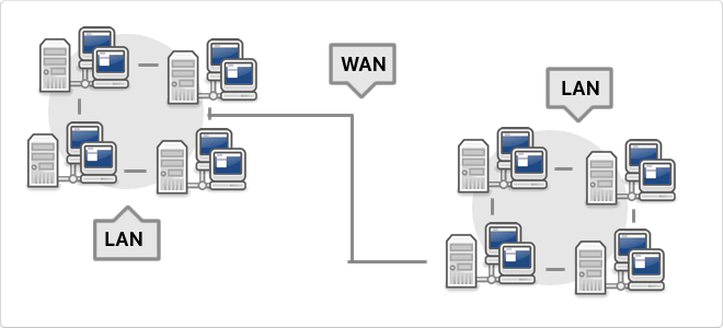
- A virtual COM port driver is provided that allowsiterate virtual serial ports with several serial servers installed in the LAN or WAN. The serial ports are completely transparent to the user and applications.
- Point to point mode (paired). This mode allows two serial servers to be interconnected through the Ethernet network. For this, one module is configured as a server and another as a client.
- Baudrate series: 300 bps at 230.4 Kbps.
- Protocols: TCP/IP, UDP, DHCP,PPPoE and dynamic DNS.
- Requires power supply from 9 VDC to 1 A (included).
- Mounted in silver metallic casing.
- 2 status indicator LEDs for each port and 4 device status LEDs.
- Size: 95 x 65 x 25 mm.
- Gross Weight: 940 g
- Number of packages: 1
- Master-pack: 1
Technical terms
- RJ45
- VDC
- RS485
- RS232
- WAN
- DHCP
- Communication Series
RJ45
When we talk about RJ45 ("Registered Jack" 45) we refer to a telecommunications network interface for wired connection of voice and data equipment.
This connector has 8 pins or connections and may have a specific category depending on the data transfer speed and bandwidth (category 5e, 6, etc.)
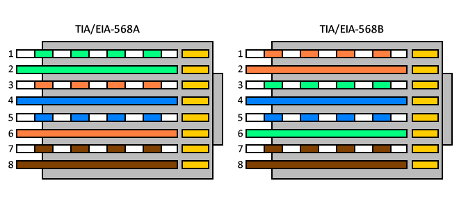
The common application is their use in Ethernet network cables under TIA/EIA-568-B standard that defines the arrangement of pins (pinout), but can also be used for other applications.
- Direct pin diagram:
EIA-568A
Pin No.1: WHITE-GREEN
Pin No.2: GREEN
Pin No.3: WHITE-ORANGE
Pin No.4: BLUE
Pin No.5: WHITE-BLUE
Pin No.6: ORANGE
Pin No.7: WHITE-BROWN
Pin No.8: BROWN
EIA-568B
Pin No.1: WHITE-ORANGE
Pin No.2: ORANGE
Pin No.3: WHITE-GREEN
Pin No.4: BLUE
Pin No.5: WHITE-BLUE
Pin No.6: GREEN
Pin No.7: WHITE-BROWN
Pin No.8: BROWN
- Schematic of crossed pins:
The crossover cable has one end with EIA-568A scheme and the other one with EIA-568B.
