04/14/2025 3:45 a.m.
https://stage.cablematic.com/en/products/ubiquiti-networks-sfp-module-uf-rj45-1g-ufiber-sfp-to-rj45-transceiver-and-converter-UI250/
https://stage.cablematic.com/en/products/ubiquiti-networks-sfp-module-uf-rj45-1g-ufiber-sfp-to-rj45-transceiver-and-converter-UI250/
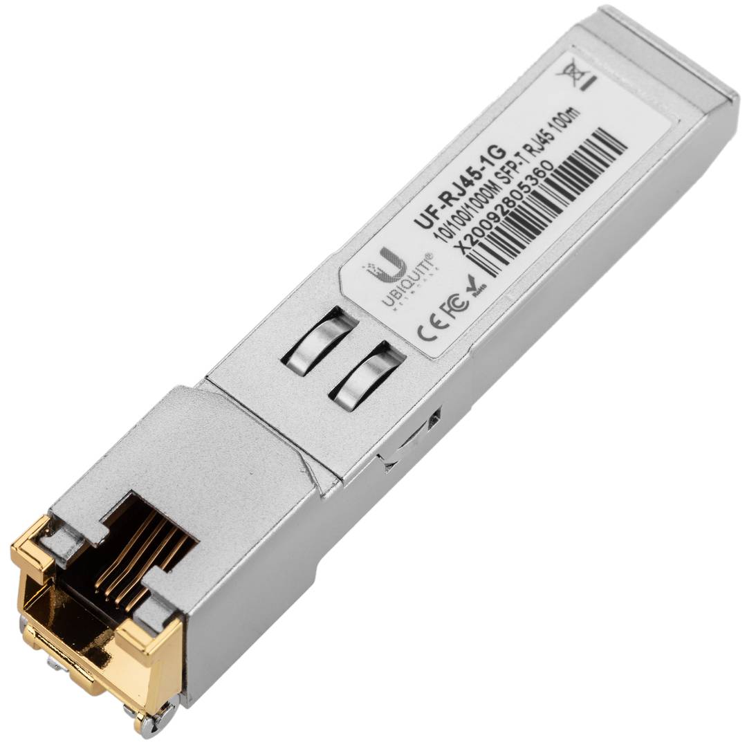
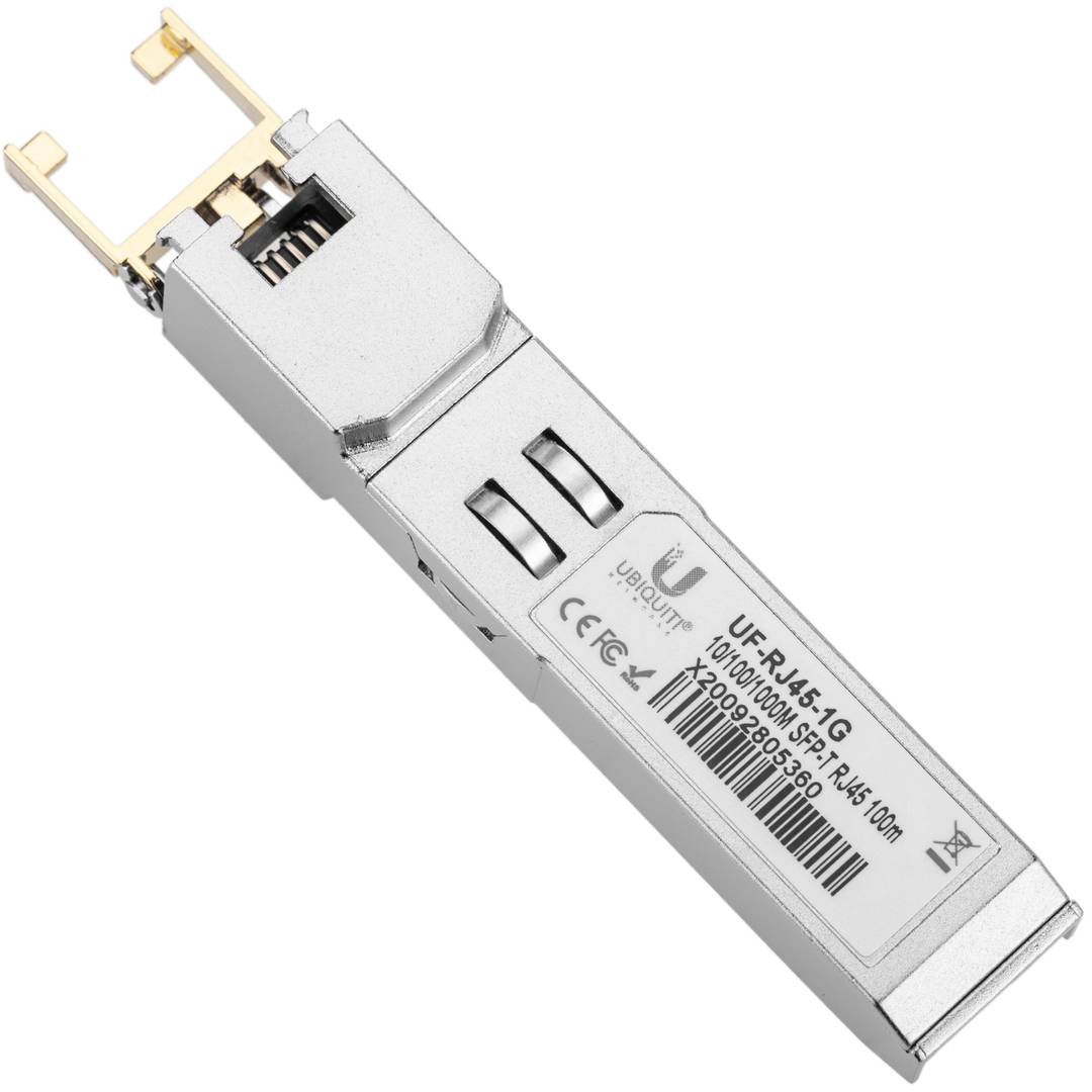
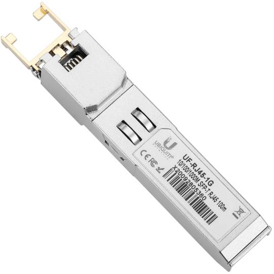
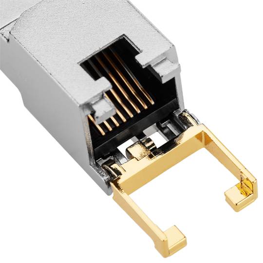
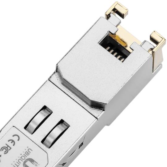
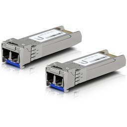
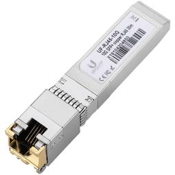
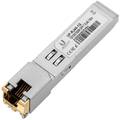
Ubiquiti Networks SFP Module UF-RJ45-1G UFiber SFP TO RJ45 Transceiver and Converter
REF: UI250
Specifications
- Module compatible with SFP or SFP + slots.
- Maximum distances of 100m with gigabit speed (1000Mbps).
- Possibility of 10/100/1000 Mbps network connection.
- Temperature range from 0 to 70ºC.
PVP
€22.49
Price including VAT:
€22.49
PVD
€18.27
PVP: Retail price.
Check conditions.
PVP: Sale price to distributors.
Check conditions.
warranty
returns
safe
Specifications
- Module compatible with SFP or SFP + slots.
- Maximum distances of 100m with gigabit speed (1000Mbps).
- Possibility of 10/100/1000 Mbps network connection.
- Temperature range from 0 to 70ºC.
More info
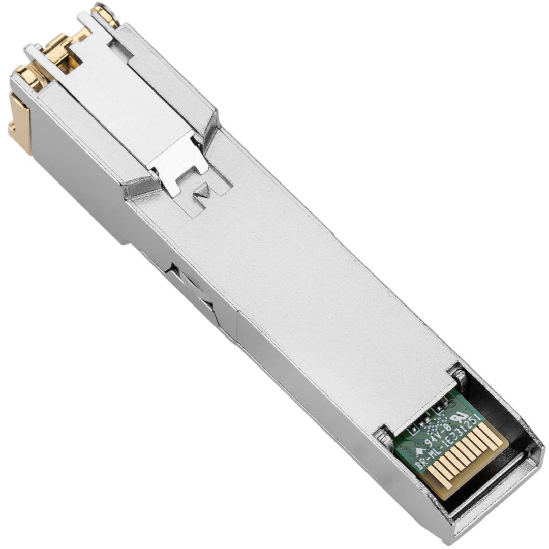
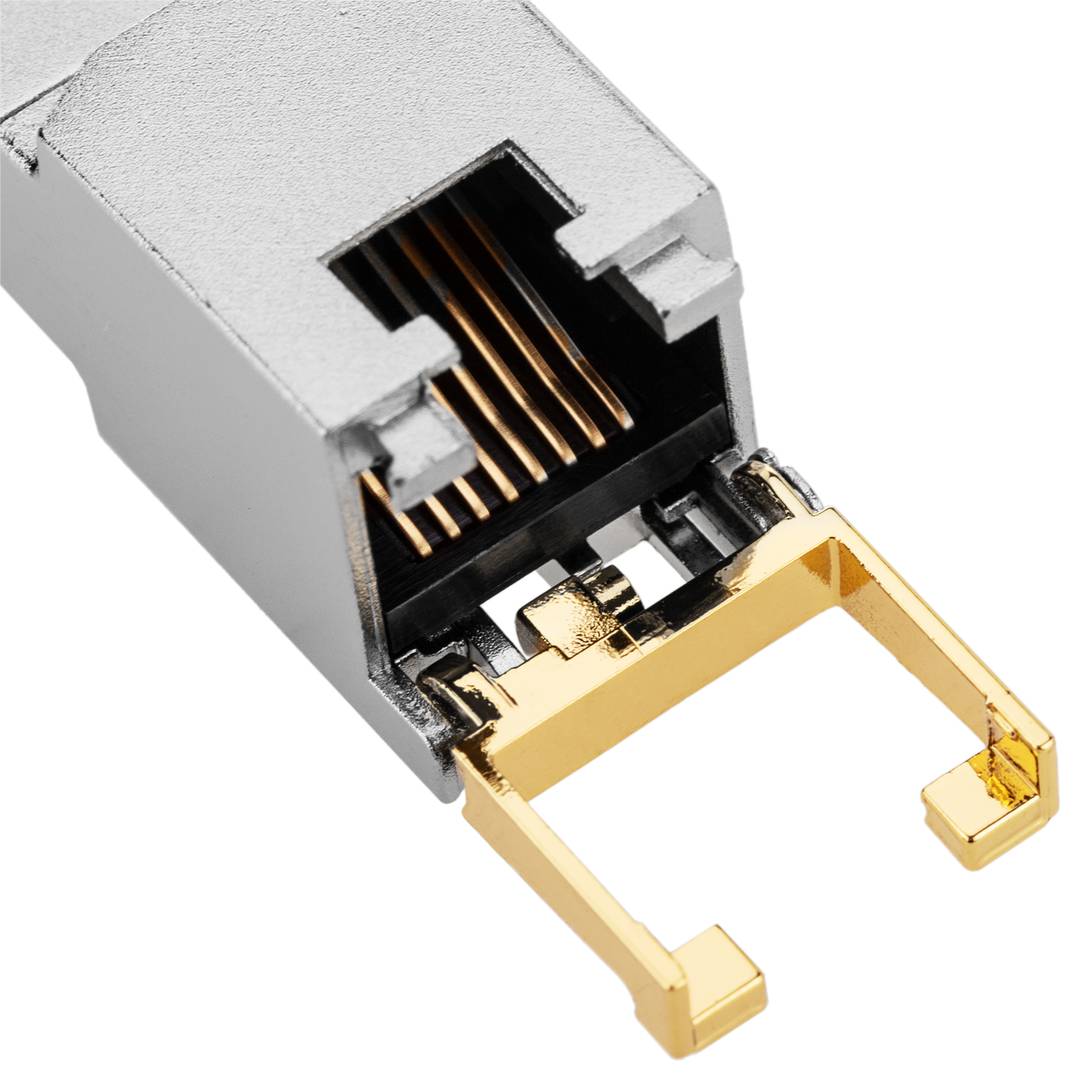
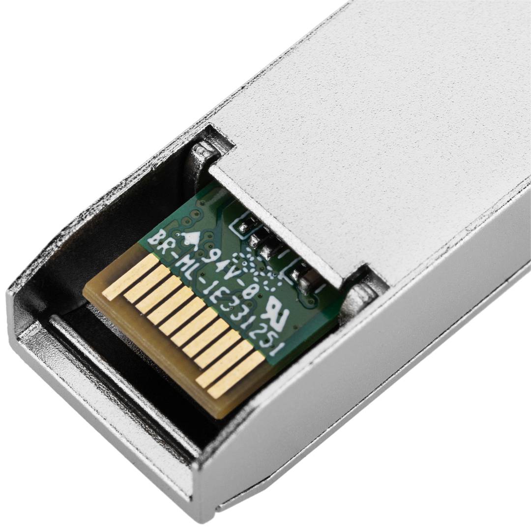
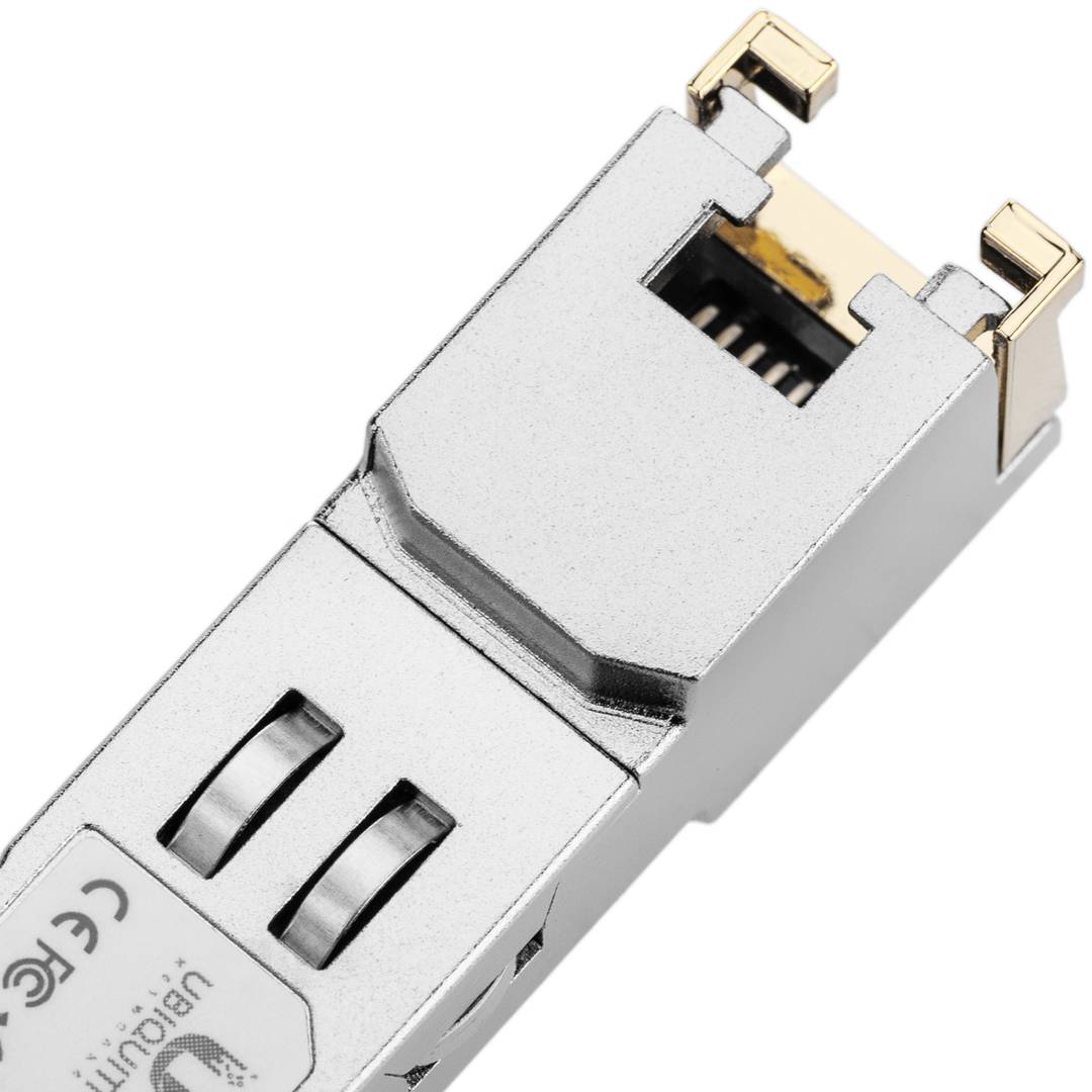
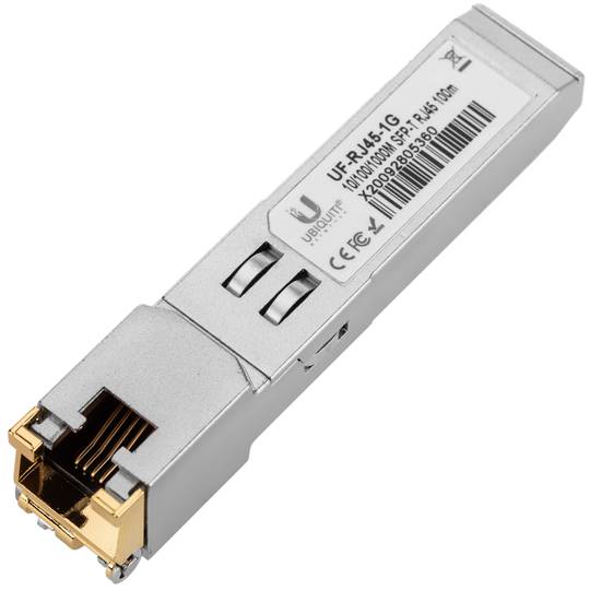
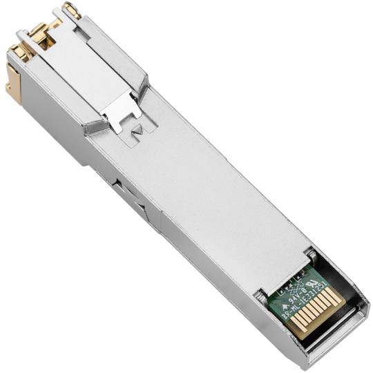
Gigabit network transceiver module with RJ45 connector to Mini-Gbic, SFP or SFP + connector from Ubiquiti Networks model UF-RJ45-1G. Maximum data transfer 1000 Mbps.
Specifications
Specifications
- Module compatible with SFP or SFP + slots.
- Maximum distances of 100m with gigabit speed (1000Mbps).
- Possibility of 10/100/1000 Mbps network connection.
- Temperature range from 0 to 70ºC.
- Gross Weight: 23 g
- Product size (width x depth x height): 7.0 x 2.0 x 1.0 cm
- Number of packages: 1
- Packages size: 8.5 x 3.0 x 1.5 cm
- Master-pack: 1
Technical terms
- GBIC
- SFP
- Gbps
- RJ45
GBIC
A Gigabit Interface Converter (GBIC, for short) is a module that is available in many forms, depending on the model and manufacturer of the brand. Each has the same function which is to increase the speed of data transfer through a network. Companies that need to transfer large amounts of data quickly, sometimes using a GBIC module for greater control and profitability. A GBIC moduleIt allows users to reconfigure fiber links, set costs of adapting the receptor and link distances network topologies and requirements established. Used in an optical fiber or Ethernet system, the GBIC modules can update, change or connect without turning off the computer. This flexibility eliminates the need to replace the entire network system together.


